Tuesday, May 28, 2013

4G15 Bottom End - Main Stud Install - ARP Mains 207-5401 & Head 201-4302


Some previous photos of a bottom end>>

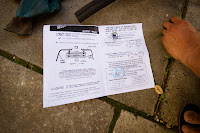
So we already hit a snag when i picked up the wrong sheet and was torquing the bolts down to 80ftlb (~111Nm) instead of the 60ftlb (84Nm).  Looks like the boxes got switched. Fun times :(
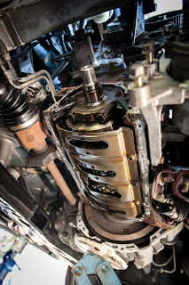


11mm bolts run a 82ftlb rating (200,000PSI).


The box has a bunch of spare bolts, i think because in the Evo the main caps/cradles use bolts.

So I started by washing the block down with detergent and give it a good clean.
Air compressor drying and sprayed it with CRC (I didn't have my WD40 on me).
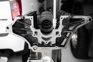


I ran a thread chaser down all the main cap threads M10x1.25. I found that when spinning them in hand tight they all didn't bottom out the same.

I cleaned all bearing caps, I used some kerosene. Good and removing oil deposits. I seen builders use Brake Kleen.

I believe the front cap (cap 1) uses bolts and not studs. Studs are a lot stronger, i believe it could be due clearance?
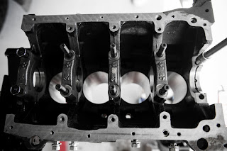


Thread cleaning and installing studs
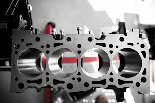


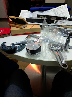
Cleaning and measuring


Ouch

I should have realised earlier, M10 run about 60ftlbs. But I guess when i saw the paper with 85, I just thought wow ok. Here we go :(

Due to this over torque, I may have over stretched them. I will conduct close measurements. ARPs are not meant to stay stretched unless you exceed their elastic limit and they won't stretch


Some of the tools i bought earlier - /tools-percision-instruments.html

ARP Sites -
Main - /instructions/207-5401.pdf
Head - /miata-arp-head-studs/
Head Bolts - /instructions/201-4302.pdf
(This is oversized M10, OEM head studs are 9mm)


My next set of plans is to clean the crank, measure the journals, redo the main caps, work out oil clearances for the bearings and install the crank. I will also attempt to measure crank walk. I didn't buy a magnetic stand, so i was planning to use feeler gauges.

After crank is installed i will re-measure the bores, pistons and start working on ring gaps and big end oil clearances.


Installation Extracts: /SBC_Main_Studs_Installation.pdf

STUDS vs. BOLTS
ARP® recommends the use of main studs over bolts whenever possible for several key
reasons. First is the ability to obtain more accurate torque readings because studs don’t
“twist” into the block. All clamping forces are on one axis. By the same token, there is
less force exerted on the block threads, which contributes to improved block life
(very critical on aluminum blocks). Finally, there are factors of easier engine assembly
and proper alignment of caps every time.

Install
There are a number of important considerations when installing ARP® main studs. First and
foremost is making sure the block and studs are as clean as possible. Foreign matter and debris can easily affect the quality of thread engagement and cause erroneous torque readings. Do not re-cut threads in the block—use the special “chaser” taps as listed on page 80 of this catalog. This will preserve the integrity of the threads and provide better engagement. You should also make sure your torque wrench has been calibrated. Even new wrenches have been known to be off by as much as 10 foot pounds!
Use consistent tightening techniques.

1. Clean and chase appropriate threads in block to ensure proper thread engagement and
accurate torque readings.

2. All hardware (and caps) should be cleaned and inspected prior to installation, looking for any shipping damage or defects.

3. Screw studs into block, finger tight ONLY. For permanent installation, apply Loc-tite (or similar adhesive) sparingly to threads. Be sure and install the caps promptly before the cement sets to prevent misalignment of studs in block.

4. Install main caps, checking for binding and misalignment. Lubricate threads, nuts and washers with oil or ARP® moly assembly lubricant before installation. Note that torque specs will vary by lubricant. Moly lube is most consistent. Have block align honed.

5. Using the instructions provided with the studs, tighten the nuts to proper torque values three times. NOTE: If using Loc-Tite or similar cement, proper preload must be achieved prior to it setting up


Monday, May 27, 2013

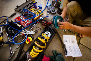
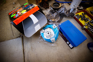
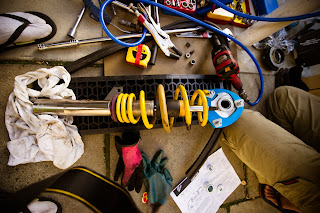
Audi A3 KW 100 1007 Suspension with K-MAC Top Hats Install


I previously installed KW on a friends Audi A3. What a bitch it was. I miss JDM suspension :(
/audi-a3-kw-front-suspension-install.html
/audi-a3-kw-rear-suspension-install.html


He decided to fit new front strut tower top hats so that he could align the suspension properly. It was also making a strange noise that we thought was the old rubber top hat breaking down.
It didn't look too bad though. We then figured it maybe the brake dust shield touching at different lock angles.


I have never installed anything so strange before. The diagrams were hard to understand as well. I will add some more info later.

Toyota FJ Cruiser TRD Big Brake Kit PTR09-35070 - Pad Replace D609 - DB439 - Part II


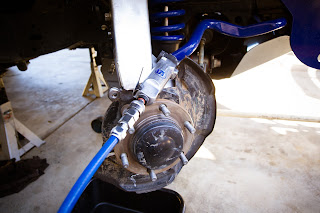
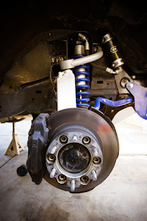
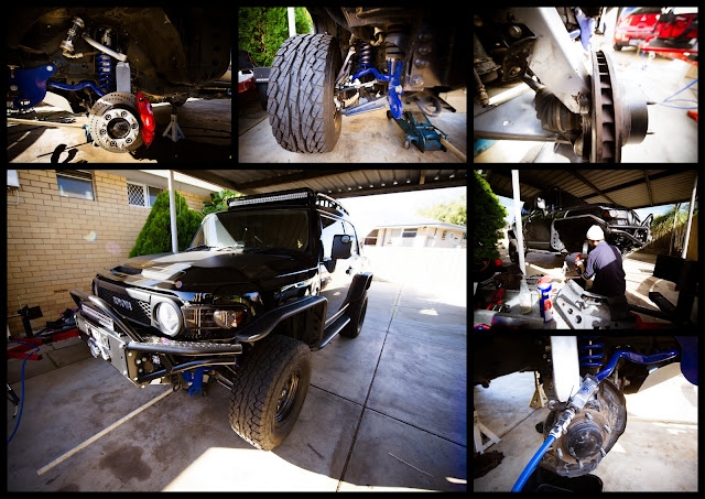
Reinstalled the TRD brakes onto another FJ. He has different hub assembly which i had to hit with the angle grinder for the brakes to clear. Nothing too major.

Nothing major. Install, bleed, cut the heat shield off the hub see here for more info


Which way do rotors turn? http://www.youtube.com/
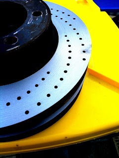
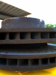
Its all about the inner vanes and not the slots/cross drilled patterns


Part 1: /toyota-fj-cruiser-trd-big-brake-kit.html


Thursday, May 23, 2013

Toyota FJ Cruiser TRD Big Brake Kit PTR09-35070 - Pad Replace D609 - DB439


My Previous Install

TOYOTA FJ CRUISER 2007 - FRONT BRAKE UPGRADE - FJ CRuiseR ’07 - ’10 pTr09-35070
Info - /10-11_TRD_Catalog.pdf
Install - /PTR09-35070inst.pdf

--------------------


30mm limit on the rotors


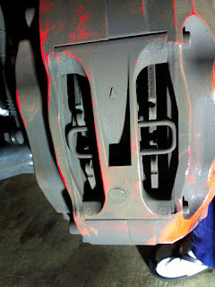
TRD Big Brake Kit - Stoptech replacement pads -  Used with the TRD BBK caliper - Brake Pad D609
TRD PERFORMANCE BRAKE FRONT RIGHT ROTOR 07-13 FJ CRUISER - PTR0935082
TRD Performance Brake Front Left Rotor 07-13 FJ Cruiser - PTR0935083

--------------------

Caliper - ST-40 - Pad Options - Stoptech, EBC, Hawk

/brake-pads/brake-pad-d609

/big-brake-kits/replacement-parts/bbk-pads-and-components/st40-components

--------------------

User - BCFDT-10
/maintenance-tech/157835-trd-big-brake-kit-question-2.html

"Installed the Stoptech street performance pads. The Axxis ones are no longer available. I paid close attention to the cleaning of the caliper and slides. I had the rotors machined as little as possible. The manufacturers recommended bed-in proceedure consists of 10 "stops" from 60 mph-5 mph with increasing brake pressure to almost lock-up, without stopping completely. Took 3 cycles of this for proper material transfer and to blue the rotors. The cold bite is about the same as the Axxis pads...strong, maybe even a little better. Modulation is great. There was no fade whatsoever during the 3 bed-ins. The Axxis pads would show some minor fade after a bed-in cycle. There is no noise or squealing, and they are supposed to be considerably less dusty than the Axxis pads, those were very dusty. I will update in a few weeks on that. Overall very pleased, and I feel they are the same or better in every aspect so far."


--------------------

Toyota Part:
TRD FJ BIG BRAKE KIT
Part NO.: PTR09-35070
Replaced By: PTR09-35100

--------------------

Part No.: HB141-Compound-Thickness

Hawk Brake Pad, Porsche 928 (D609)

FMSI D372, D447, D609.
Fits:
1994-98 Audi RS2
1994-96 Ferrari 456 GT Coupe Rear

and many Porsche models, including:
1996-98 911 Carrera 4 rear
1991 911 Turbo
1986 928 S
1987-91 928 S4
1990-91 928 GT
1989-91 944 Turbo
1992-95 968 Sport
Also fits the Stoptech ST40 caliper.

--------------------

Bendix Website - DB439

Aftermarket Upgrade Kit / Caliper Stoptech ST-40 1999 - NOW

Set Consists of - 4 Pads 132 x 70 x 18 mm

I have Purchased DB439HPX - QFM HPX

-------------------- Extract From Install PDF --------------------

Kit Contents
Item # Quantity Reqd. Description
1 1 Brake Rotor, LH Front
2 1 Brake Rotor, RH Front
3 1 Brake Caliper Assembly, LH
    Front with 2 M12X30mm Allen
    Head Socket Bolts
4 1 Brake Caliper Assembly, RH
    Front with 2 M12X30mm Allen
    Head Socket Bolts

Hardware Bag Contents
Item # Quantity Reqd. Description
1 2 Stainless Steel Brake Hose
2 2 Banjo Bolt
3 2 Rubber End Cap
4 4 Copper Washer
5 1 Dust Shield Template
6 1 Installation Instructions
7 1 Mirror Hanging Tag
8 1 Owner’s Document

Recommended Tools
--- Personal & Vehicle
Safety Glasses Safety Glasses /face shield
Vehicle Protection Seat & Floor Covers
Fender Covers
Work Gloves
Special Tools Notes
Chassis Lift or (Hydraulic Jack & Jack
Stands)
Fluid Drip Trays One per side
Air Powered Vacuum With chip collection bag

--- Installation Tools Notes
21mm Deep Socket ½” Drive
Air Impact Gun ½” Drive
10mm Flare Nut Wrench
Needle Nose Pliers
17mm Deep Socket ½” Drive
Air Powered Nibbler
Torque Wrenches 3/8” & ½” Drive
9/16” Socket 3/8” Drive
Soft Mallet
11mm Combination Wrench
10mm Allen Socket 3/8” Drive
Breaker Bar ½” Drive

--- Special Chemicals Notes
Toyota Brake Fluid #00475-1BF03 or Fluid:
SAE J1703 or FMVSS No.
116 DOT3
Toyota Brake Cleaner #00289-2BC00-CA

Tools & Percision Instruments


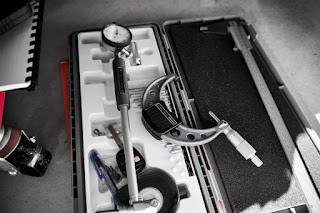
I finally decided to bite the bullet and buy some precision instruments. These will in turn aid my engine rebuild that i would like to do myself.
I have started of with purchasing some Mitutoyo Micrometers and a vernier http://www.mitutoyo.com.
I will soon add Starrett http://www.starrett.com telescopic gauge set or if i decide to get a cheaper set i will be looking at the Draper set.

Good Read:
/specialty-tools-for-performance-engine-building/
/connecting-rod-bolts-stretch-vs-torque/


More Details On The Build List
Engine Assembly
Pick List
/generic-servicing-tools.html

I have also been keeping an eye on a tap and die set. Hansen, Irwin or Kincrome not idea what to look. I ended up with a KCTools unit. Pretty nice. It has come in handy plenty of times so far :)
Vernier Caliper
Reading: /how_to_read_a_vernier_caliper.html
Video: Reading Metric Vernier


Micrometer
Reading: /reading_a_metric_outside_micrometer.html

Vernier Micrometer
I wish i could afford a vernier micrometer :(
/vernier_micrometer.html

Dial Indicator
Items from Mitutoyo: http://www.mitutoyo.co.jp/
Quick Guide: Quick Guide Dial-Indicators.pdf
Video: How to Use a Dial Indicator
Video: Measuring Runout

Dial Bore Indicator
I just got one of these. I will use snap/telescopic gauges to measure sub 50mm and 50mm-150mm i will use the dial bore gauge.
I have a set of micrometers from 0-100mm (4 micrometers complete this range)

http://www.farnell.com/

Fixed Probe Type:
1. Remove dial indicator from protective shroud.
2. Insert indicator stem into top of bore gauge.
3. Position indicator into bore gauge stem with one revolution of dial gauge hand. Use knurled thumbscrew on split clamp to
clamp indicator.
4. Select probe and shim washer to get nearest to required measurement size.
Example : Measurement size: 2.750 inches
Select probe 2.6 inches shims 0.1 and 0.05 = 2.75 inches
5. Fit shim washers behind datum flange on probe.
6. Remove knurled retaining nut from bore gauge foot and insert probe with shims.
Replace retaining nut and clamp probe positively.
7. At this stage it is necessary to offer the bore gauge to a setting master at the required nominal size.
This can be a ring gauge, caged gauge blocks with protruding end faces or a pre-set micrometer.
8. Insert bore gauge probes into the ring gauge or between the faces of the setting master.
9. Rock bore gauge in ring or between the setting master faces to achieve the reversal point of the indicator hand.
If this does not coincide with the zero on the dial, re-position dial gauge down bore gauge stem to achieve this position.
The final setting of zero can be made by rotating dial gauge bezel so that the zero coincides exactly with the reversal point at the
indicator hand.
Re-check in setting gauge.
Finally replace protective shroud and clamp firmly to top of bore gauge ste


Screwed Probe Type:
1. Remove dial indicator from protective shroud.
2. Insert indicator stem into top of bore gauge.
3. Position indicator into bore gauge stem with one revolution of dial gauge hand. Use thumbscrew on split clamp to clamp indicator.
4. Select a probe with a range which suits the required measurement size.
5. Fit knurled lock nut to probe.
6. Screw probe into bore gauge foot.
7. Select setting master (see previous instructions).
8. Insert bore gauge probes between setting master faces and adjust screwed probe to bring dial gauge hand to zero position.
9. Rock bore gauge probes in ring or between the setting master faces to achieve the reversal point of the dial indicator hand.
10. Fine adjust dial hand to zero by either adjusting screwed probe, moving dial indicator up or down in bore gauge and finally
revolving bezel to obtain final zero.
Taking Measurements:
1. Insert pre-set bore gauge into component hole.
2. Rock bore gauge in hole.
3. Note reversal point of dial guage hand.
4. Add or deduct the variance from zero to the setting master nominal size, to obtain the measured diameter of the component hole


Measurements
 My plan is to measure everything I can, I am planning to start with:
  Cylinder Heads & Valves: 
    - Gasket surface warp
    - Cylinder head overall height
    - Valve length
    - Valve spring free height
    - Valve stem-to-guide clearance
    - Valve guide length
    - Valve guide projection
            - i read that you can install valve guides with ether/alcohol and dry ice, if you don't have liquid nitrogen.
    - Valve projection from valve spring seat

  Pistons & Rings: 
    - Piston wrist pin diam/length
    - Piston wrist pin clearance
    - Wrist pin retainer
    - Piston diam

    - Top ring type / width / end gap
    - 2nd ring type / width / end gap
    - Oil ring type / gap

    - Desk height per piston (the amount the piston is above or below the desk - compression calcs)

  Rods: 
    - length
    - big end with/without bearing
    - small end
    - workout oil clearance
    - thrust clearance

  Crankshaft: 
    - end play
    - oil clearance at crankshaft journals

More Details On The Build List
Engine Assembly
Pick List

Other Handy Tools
Rotabroach
Rotabroach® Annular tools cut clean, burr-free, round holes fast, unlike twist drills that push or hole saws that tear thru materials. Because they're hollow, they cut around the edge of the hole, so less work is required and no deforming of material or jagged edges occur. Multiple cutting teeth are precision ground instead of stamped like hole saws, give long tool life.
/Rotabroach_Cutters/rota_cutters.html

Thread Restorer...............Rethreader............ Thread Chaser
NOTE: Tap and die sets are not the same as threadchasers


A Restorer is a 2 bladed tool that looks a lot like a big tap wrench. It's applied to a good point in the threaded rod, and turned along the bunged up thread pushing the metal back into place. It's useful on soft steels and brass threads, and totally useless on hard materials. In the hands of an amature it's a good way to insure nobody can fix it.

A rethreader is a tool that preforms the same function as a restorer, but does the job a bit differently. The rethreader is similar in appearance to a die, BUT, is ground to push threads back into place, rather than cut threads.

It's possible to make your own thread chaser by taking a bolt with the correct thread and cutting 3 or 4 vertical slots equidistant from each other on the length of the bolt threads. The depth of the cut should be down to just beyond the minor diameter of the thread.

Just to add a to this, make sure to use a grade 8 or better bolt! Also make sure the slots are evenly spaced and the threads are thoroughly de-burred after the slots are cut, use a soft bolt, poorly cut slots or fail to de-burr and it is very easy to get a home made thread chaser cross threaded in the hole.  It is a good idea with these home made chasers to run a proper sized nut onto the modified bolt several times using anti-seize before attempting to repair any damaged threads with it.

To repair spark plug threads just go to almost any auto parts and buy a spark plug chaser, it will be double ended with both common thread sizes. This thing is probably no harder than a grade 8 bolt and will not cut threads but with a little anti-seize applied will easily repair most Aluminum head spark plug threads as well as most cast iron heads.


A chaser is a cutting die that brings a rough cut thread or a plated thread back to dimension by cutting. Chasers are not designed to cut threads from raw stock, they have more teeth than a normal die has, so less clearance for chips to leave the die. Chasers are normally run at higher speeds than dies.

Thursday, May 16, 2013

My Sample Engine Build Guide - Upcoming 4G15 Forged Build

Notes gathered from:
 - http://www.speedprint.com/

Further Details

 - /rcolt-rebuild-pick-list-part-numbers.html
 - /teaching-myself-engines-fact-finding.html
 - /generic-servicing-tools.html

Tools:
 - Engine stand & crane
 - torque wrench - flex beam
 - hammer with plastic or wood handle
 - spanners and sockets
 - assembly lube
 - oil - mineral oils / run in oil
 - gasket sealer - oil pan and head
 - engine paint
 - freeze plug installer
 - thread sealer


Hardcore Tools:
- snap/telescopic gauge - measure IDs
- dial bore gauge
- valve spring compressor
- stretch gauge
- ring compressor
- ring expander pliers
- dial indicator (measure crank end play)

Precise Measurements:
- piston to wall clearance therefore: measurements of cylinder bores and piston heads
- measure the crank main bores - snap gauge or dial bore gauge
- crank main journals + main bearings
- crank cradle bolted down with plasti gauge - compare results to crank main journal measurements (measured with snap gauge etc)
- rod caps on and torquing to spec, measure the bore diameter
- rod to crank clearances:  Rod race diameter minus bearing thickness X 2 + rod journal diameter
- plasti gauged the rod bearings. Install the clean bearings in the rod and rod cap. Bolt them to the crank with a piece of plasti gauge and torque to spec
- ring gap


Build:

Cleanliness cannot be over stressed!

Pre-Assembly:
 * clean the threads of any bolts to be re-used.
 * Check all gasket and seal mating surfaces for warpage and bent or damaged areas which could result in sealing failures. Clean all gasket surfaces of oil, paint, etc.
 * Prime the oil pump with engine oil or assembly lube before installing it on the new engine
 * clean the oil pickup tube and screen
 * Only use gasket adhesives/sealers where required by the gasket manufacturer

Assembly:
 * Use a thread sealer where bolts enter any fluid areas, (coolant or oil) to prevent leakage around threads
 * Install a new water pump
 * Install new belt drives
 * Install new timing belts and any idler/tensioner pulleys that the timing belt contacts
 * Inspect motor and transmission mounts
 * Inspect the clutch, flywheel, flex plate
 * Fill the new oil filter with motor oil before installing.
 * Fill the engine with break-in oil
 * Prime oil system, i remove the fuel pump and ignition and use the starter to spin the crank and in turn spin the oil pump.
 * Install new spark plugs
 * Install new air filter, fuel filter, crankcase filter and PCV valve
 * Fill the cooling system with a 50/50 mixture of new antifreeze/coolant and distilled water.

If the recommended parts above (hoses, belts, water and fuel pumps, spark plugs, etc.) are fairly new and still in “like new” condition, then it will probably be OK to re-use them.

Engine Clean:
 - Re-move galley plugs & brush out all oil galleys.
 - Use soap and water to wash out cylinders then completely dry with air & linen (no lint), and use light oil in lifter bores, main bore, cylinder walls, etc., after washing.

Crankshaft Installation Guide:
 * before dissassembly all parts should be labels and orders kept. E.g. connecting rods, main caps, rod caps etc
 * Check connecting rod housing bores for roundness and size using bore gauges or inside micrometers
 * Check main bearing bores for alignment and size. This should be done by a shop, they can realign the bores.
 * Clean oil passage in crankshafts
 * Clean oil passages in engine
 * Clean main bearings bores (clean and dry)
 * Check oil hole alignment. Bearing locating tangs lines up to feed the oil holes
 * You can do a dry fit and use Plastigauge, check tolerances.
 * Lube bearing surfaces (use assembly lube)
 * Gently and squarely place the crankshaft onto the main bearings. Care should be taken to prevent damage to the bearing flange thrust surfaces. Main caps and bearings must then be installed in proper positions.
 * All bolt threads must be cleaned and lightly lubricated to obtain correct torque readings. Final tightening of all bolts must be in accordance with engine manufacturer's specifications. Crankshaft should rotate freely after tightening procedure
 * Before installing piston and rod assemblies, rod bolt threads must be covered to prevent damage to crankshaft journals. It is common to use some rubber hose, try and guide the piston down the main bores.
 * Ring gaps need to be set, measure rings and file down if needed. Rings can be measured by placing them inside the bore and using the piston to square them up and a feeler gauge to measure.
 * Install rings to pistons, lube bores and wrist pins. Assembly lube can be used for the wrist pin where the bores can use engine oil.
 * Match rod caps in accordance with cylinder numbers on connecting rods. Torque rod bolts or nuts to manufacturer's specifications.
 * By using a feeler gauge, check for proper end clearance between crankshaft thrust and bearing flange to manufacturer's recommendations.

Break in:
After rebuilding your engine, the first few minutes of engine operation are the most critical. Be sure that you do not allow your engine to run under 1500 RPM’s for the first five minutes to one hour! Research tests have shown that if there is no metal pickup (or spalling) during this period, your camshaft will wear as long or longer than the engine’s other components.

Inital Startup Checklist:
 * Monitor oil pressure gauge/light
 * Visually check for fluid leaks.
 * Listen for any unusual noises, (knocking, tapping, scraping, etc.
 * Monitor the engine temperature gauge as the engine warms up
 *

Breakin Checklist:
 * NOTES: Alot of people use mineral oils as breakin if not using breakin oils. You should wait a few 1000km before switching to synthetic oils.
 * Detergent keeps the impurities in suspension, so when the oil is drained, the crap comes out.
 * Oil FAQ http://www.morrislubricants.co.uk/lubricants/company.asp?wp=90


 * Constantly monitor gauges/warning lights
 * Check the fluid levels daily, correct as needed
 * Check for fluid leaks daily
 * Change the oil and filter at 200 miles, 1000miles, 2000 miles and every 3000 miles or three months thereafter

 * 100miles = 160km

 ******The first 200 miles of the engines life should be ran at mostly highway and varying speeds.

Sunday, May 12, 2013

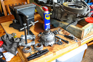
How to remove bearings off a differential LSD and RColt Stock Diff Comparison


OK. So i sold my Quaife. I swapped to an ATS LSD? Because i am crazy.
So i had to finally pull apart my smashed gearbox and inspect. Its been sitting for around six months. Everything was sealed and left oiled. So apart it came. Then i decided to test drive my bearing splitters. WOW they worked.
With some retro fitting i was able to remove the bearings.


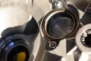
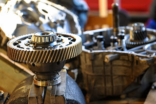
Looks like the ring gear came in contact with the bearing race. Not to much damage to the ring gear or the output shaft gear.


Sad days, the crack :(


Because the bearing race came loose in the housing it has some wear marks. Nothing major. Bearing were all intact and still spinning

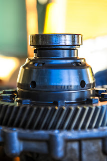
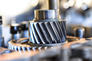
Output shaft close up


Ring gear close up


Extracted


More of the crack


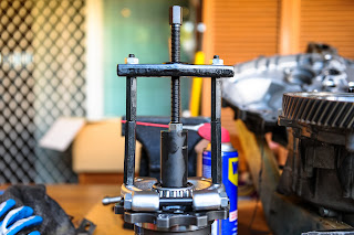
Ring gear removal.


My modified bearing puller. I used a socket to sit directly on the LSD. I then use a nut to free spin between the bearing splitter and the socket.
I lubed it all up due to the tension i knew would be on the parts.


No need for a butane torch, sweet!


And both successfully removed. I used the rattle gun to slowly drive the bearing splitter tool


Internal photos of the stock differential


Honda P30A Rebuild/Overhaul from a B18C EG Engine Swap


FAKKKKKKKKKKKKKKK
I had a complete blog enter and i accidentally hit reload :( I am sure this version will be very simplified because i am pissed.


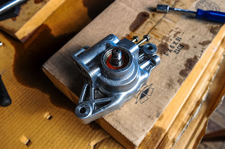
Removing the pump 12mm, 14mm and 10mm is all you should need. 19mm for the pulley.
NOTE crack all bolts before removing the pump.
ALSO NOTE THE PULLEY IS REVERSE THREAD.


One of the hydraulic line orings.


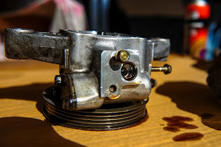
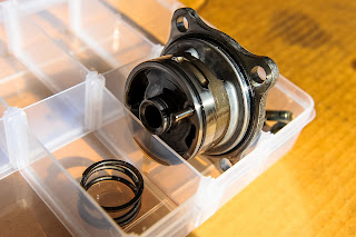
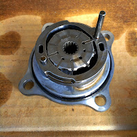
The main part of the pump. In here is a magnetic base that hold the floating.... AH
i forgot the name. Anyways becareful pulling it apart, you might lose the fins


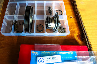
oring kit with the power steering shaft seal and bearing.


NOTE POWER STEERING SHAFT PULLEY IS A REVERSE THREAD.


You can see the circlip that needs to be removed prior to punching out the bearing and shaft.


Due to the leaking unit I had to clean the whole thing in kerosene and a toilet brush.


Punch it out via the opposite side. Use a rubber hammer so you done damage the shaft.


All the internals of the pump


The shaft. A real bitch to get out. But keep trying it will come!


 Removing the bearing was another pain in the ass. But doable


 Old vs new


Another close up kit of the package i got for the rebuild.


 Bearing housing

Pressing on the new bearing, the socket is rest on the inner race of the sealed bearing.


The vanes and the internals of the pump.


 DONT LOSE THESE


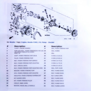
This is a rough breakdown of a pump. I used it as a guide line to know what inside.


A universal o ring kit i got for backup!


The belt of the pump